
There is a moment in every hardware engineer’s career when they realize that guessing the required torque for a hinge is a terrible idea. Usually, this realization happens right after a heavy industrial cabinet lid slams shut on someone’s fingers, or when a premium laptop screen slowly droops backward because the hinge can’t hold its own weight.
If you are designing a product that requires a friction hinge (also known as a torque hinge or position control hinge), you cannot rely on trial and error. The math is not optional; it is the foundation of a safe, reliable, and premium-feeling product.
However, the good news is that the calculation is not as complex as you might fear. In this comprehensive guide, we will break down exactly how to calculate torque for a friction hinge, explain the variables that everyone gets wrong, walk through real-world examples, and show you how to apply the correct safety margins so your product never fails in the field. Discuss more on Whatsapp
The Core Formula: The Physics of Position Control
Before we dive into the calculations, let’s establish what torque actually is. In the context of a friction hinge, torque is the rotational force required to move a panel around a pivot point, or conversely, the resistance required to hold that panel in place against the force of gravity.
To calculate the torque required to hold a lid or panel, you need to use the fundamental physics equation for torque:
Torque (T) = Force (F) × Distance (D)
However, when dealing with a physical panel attached to a hinge, we need to adapt this formula to account for gravity, the panel’s center of gravity, and the angle of opening. The complete, practical formula for friction hinge torque calculation is:
T = W × L<sub>CG</sub> × cos(θ)
Let’s break down exactly what each of these variables means.
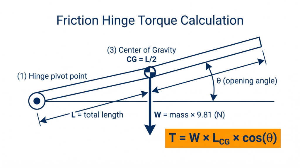
Figure 1: The fundamental physics of calculating torque for a friction hinge.
1. T = Torque (Required Resistance)
This is the final number you are looking for. In the metric system, torque is typically expressed in Newton-meters (N·m) or kilogram-force centimeters (kgf·cm). In the imperial system, it is usually expressed in inch-pounds (in-lbs). This number tells you how strong your friction hinge needs to be to hold the panel in place.
2. W = Weight (Force due to gravity)
This is where the first common mistake happens. People often confuse mass with weight. If your panel has a mass of 5 kilograms, its weight (the force it exerts downwards due to gravity) is not 5.
To find the weight in Newtons (the standard unit of force), you must multiply the mass in kilograms by the acceleration due to gravity (9.81 m/s²).
W = Mass (kg) × 9.81
If you are using the imperial system, the mass in pounds (lbs) is generally treated as the force in pounds-force (lbf) for these calculations, making the math slightly more direct but often confusing when converting to metric.
3. L<sub>CG</sub> = Distance to the Center of Gravity
This is the distance from the hinge pivot axis to the center of gravity (CG) of your panel.
If you have a perfectly uniform, flat panel (like a simple piece of sheet metal or a solid wooden board), the center of gravity is exactly in the middle. Therefore, L<sub>CG</sub> = Total Length / 2.
However, if your panel has heavy components mounted on it—such as a thick glass screen, a heavy handle at the edge, or an internal motor—the center of gravity will shift. You must calculate or measure the exact distance from the hinge to this new, shifted center of gravity.
4. cos(θ) = The Angle Factor
The amount of torque required to hold a panel changes depending on the angle at which it is open.
•When the panel is perfectly horizontal (0 degrees), the force of gravity is acting perpendicular to the panel. This is when the maximum torque is required. Since cos(0°) = 1, the formula simplifies to T = W × L<sub>CG</sub>.
•When the panel is perfectly vertical (90 degrees), the center of gravity is directly above the hinge. The force of gravity is pulling straight down through the pivot point, meaning zero rotational force is generated. Since cos(90°) = 0, the required torque is zero.
Because a friction hinge must be able to hold the panel at its heaviest point, you must always calculate for the peak torque, which occurs when the panel is horizontal. Discuss more on Whatsapp
3 Real-World Calculation Examples
To make this abstract formula concrete, let’s walk through three common engineering scenarios. We will calculate the peak torque (when the panel is horizontal, so cos(θ) = 1) for each.
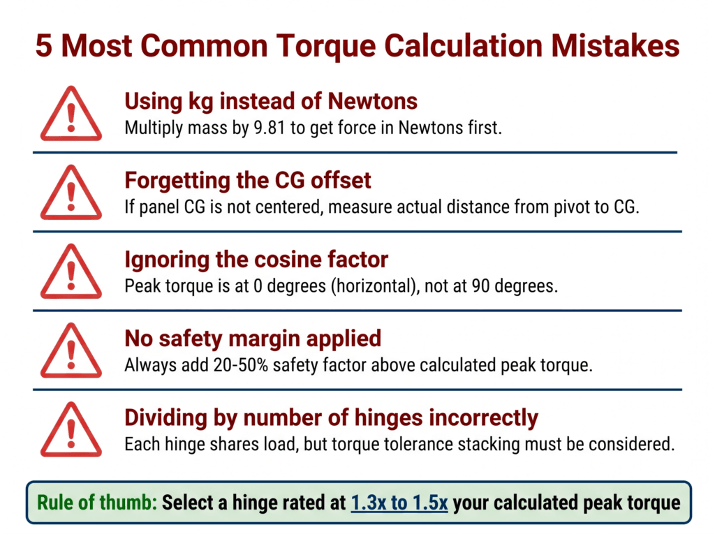
Figure 2: Three common real-world scenarios for torque calculation.
Example 1: The Consumer Electronics Laptop Screen
You are designing a ruggedized laptop. The screen assembly has a mass of 0.4 kg, and its total height (length from the hinge) is 28 cm (0.28 meters). The weight is evenly distributed.
1.Find W (Force in Newtons): 0.4 kg × 9.81 = 3.924 N
2.Find L<sub>CG</sub> (Center of Gravity): 0.28 m / 2 = 0.14 m
3.Calculate Peak Torque: T = 3.924 N × 0.14 m = 0.55 N·m
To hold this screen horizontal, the hinge system must provide at least 0.55 N·m of resistance.
Example 2: The Heavy Industrial Cabinet Lid
You are designing a top-opening control box for a factory floor. The solid steel lid has a mass of 3.5 kg. The lid is 50 cm (0.5 meters) long.
1.Find W (Force in Newtons): 3.5 kg × 9.81 = 34.335 N
2.Find L<sub>CG</sub> (Center of Gravity): 0.5 m / 2 = 0.25 m
3.Calculate Peak Torque: T = 34.335 N × 0.25 m = 8.58 N·m
This is a substantial amount of force. A standard consumer hinge will fail instantly; you need an industrial-grade heavy-duty friction hinge.
Example 3: The Medical Monitor Arm
You are engineering a tilt arm for a patient monitoring screen. The monitor itself has a mass of 2.2 kg, and the arm length from the pivot is 40 cm (0.4 meters). However, the monitor is mounted at the very end of the arm, meaning the center of gravity is not in the middle of the arm, but at the end (0.4 meters).
1.Find W (Force in Newtons): 2.2 kg × 9.81 = 21.582 N
2.Find L<sub>CG</sub> (Center of Gravity): 0.4 m (Because the heavy monitor is at the end, we use the full length, not half).
3.Calculate Peak Torque: T = 21.582 N × 0.4 m = 8.63 N·m
Notice how the uneven weight distribution drastically increases the required torque compared to a uniform panel.
The 5 Most Common Torque Calculation Mistakes
Even experienced engineers occasionally slip up when specifying friction hinges. If your prototype fails, it is almost certainly due to one of these five common calculation errors.

Figure 3: Avoid these five common errors when specifying a torque hinge.
1. Using Mass (kg) Instead of Force (Newtons)
This is the number one reason calculations fail. If you multiply 5 kg by 0.5 meters, you get 2.5. But 2.5 what? It’s not Newton-meters. If you order a 2.5 N·m hinge for this application, it will immediately fail, because the actual required torque is 24.5 N·m (5 kg × 9.81 × 0.5 m). Always multiply your mass in kilograms by 9.81 to get Newtons before calculating torque.
2. Forgetting the Center of Gravity Offset
As shown in the medical monitor example above, the formula L / 2 only works if the panel is a perfectly uniform rectangle with evenly distributed weight. If you attach a heavy handle to the edge of a lid, the center of gravity moves outward, increasing the LCG distance and drastically increasing the required torque. Always find the true center of gravity.
3. Ignoring the Safety Margin (The 1.3x Rule)
Calculated torque is the absolute minimum force required to hold the panel in a static, perfect environment. The real world is not perfect.
•Users will push down on the lid.
•Vibrations in machinery will cause micro-movements.
•Torque decay (the natural loss of friction over tens of thousands of cycles) will reduce the hinge’s holding power by 10% to 15% over its lifespan. Discuss more on Whatsapp
The Golden Rule: Always select a friction hinge with a rated torque that is 30% to 50% higher than your calculated peak torque. If your calculation says you need 5.0 N·m, specify a hinge rated for 6.5 N·m to 7.5 N·m.
4. Miscalculating for Multiple Hinges
Most lids and panels use two hinges (one on the left, one on the right) for stability. The math here is simple: if your total required torque is 10 N·m, you can use two hinges rated at 5 N·m each.
However, the mistake occurs when engineers forget about manufacturing tolerances. A hinge rated at 5 N·m might have a ±15% tolerance, meaning it could output anywhere from 4.25 N·m to 5.75 N·m. If you get two hinges on the low end of the tolerance (4.25 + 4.25 = 8.5 N·m), your lid will fall. This is why the 30% safety margin mentioned above is absolutely critical when dividing load across multiple hinges.
5. Confusing Symmetric vs. Asymmetric Torque
Standard friction hinges have symmetric torque, meaning they offer the same resistance whether you are opening or closing the lid.
However, gravity only works in one direction. When opening a heavy lid, the user is fighting gravity and the friction hinge. When closing the lid, gravity is helping, so the user feels much less resistance. This can result in a lid that is very hard to open but slams shut too easily.
If your calculated torque is very high (e.g., over 5 N·m), you should strongly consider an asymmetric friction hinge. These hinges provide high resistance in one direction (to hold the lid up against gravity) and low resistance in the other direction (so the user can easily lift the lid). Discuss more on Whatsapp
When to Use a Torque Hinge vs. A Gas Spring
As you run your calculations, you may find that your required torque is exceptionally high. Friction hinges are incredible pieces of engineering, but they have physical limits.
If your calculation results in a required torque exceeding 15 N·m to 20 N·m, a friction hinge might no longer be the best choice. At these high torque levels, the user will have to exert massive physical effort just to overcome the hinge’s resistance to open the lid.
For extremely heavy applications—such as large boat hatches, heavy machinery hoods, or massive industrial enclosures—you should transition from a friction hinge to a gas spring (gas strut). Gas springs actively push the lid open, assisting the user, whereas friction hinges only provide passive resistance.
If you are unsure which technology fits your application, read our detailed guide on How to Choose Torque Hinges vs. Gas Springs.
Frequently Asked Questions (FAQ)
1. What is the difference between kgf·cm, N·m, and in-lbs?
These are simply different units of measurement for torque.
•1 N·m ≈ 10.2 kgf·cm
•1 N·m ≈ 8.85 in-lbsMost global hinge manufacturers use N·m as the standard, but American suppliers often use in-lbs. Always double-check your units before ordering prototypes.
2. Does the width of the panel affect the torque calculation?
No. The width of the panel (the dimension parallel to the hinge axis) does not affect the torque calculation. Only the mass of the panel and the length (the distance extending outward from the hinge axis) affect the torque. However, a very wide panel might require more hinges to prevent the material from bowing or flexing in the middle.
3. How do I account for a lid that only opens to 45 degrees?
If a lid physically cannot open past 45 degrees due to a hard stop, the peak torque it will ever experience is at 45 degrees. You would calculate this using T = W × LCG × cos(45°). Since cos(45°) is roughly 0.707, the required torque is only about 70% of what it would be if the lid could open to horizontal (0 degrees).
4. What happens if I choose a hinge with way too much torque?
If you calculate that you need 2 N·m, and you install a 10 N·m hinge “just to be safe,” the panel will be extremely difficult for the user to move. Furthermore, the excessive rotational force will put immense stress on the mounting screws and the panel material itself, potentially causing the plastic or metal housing to crack or warp over time. Stick to a 30% to 50% safety margin.
5. How do I calculate torque for a curved or irregularly shaped lid?
For non-uniform shapes, you cannot simply divide the total length by two to find the center of gravity. You must use CAD software (like SolidWorks or AutoCAD) to calculate the exact center of mass for your specific 3D geometry. Once the software gives you the exact distance from the pivot axis to the center of mass, you plug that distance into the standard Lcg variable in the formula.
Need Help Specifying Your Hinge?
Calculating torque is only the first step in the engineering process. Once you have your numbers, you still need to select the right materials, determine the optimal cycle life, and navigate manufacturing tolerances.
If you are designing a new product and need expert guidance, the engineering team at JAN Hinge can help. We specialize in designing and manufacturing custom friction hinges for aerospace, medical, industrial, and consumer electronics applications. Send us your panel dimensions and weight, and we will calculate the exact torque specifications required for your project.
Advanced Considerations for Torque Hinge Selection
While the core formula T = W × LCG × cos(θ) will get you 90% of the way there for most applications, professional engineering requires considering edge cases. Let’s explore the advanced factors that separate a good hinge implementation from a flawless one. Discuss more on Whatsapp
Temperature and Environmental Impact on Torque
Friction hinges rely on the physical interference between materials—often a combination of steel bands, friction clips, and specialized greases. These materials react to temperature changes.
•In extremely cold environments (e.g., an outdoor kiosk in winter), the grease thickens, and the metal components contract. This can temporarily increase the friction torque, making the hinge feel stiffer than calculated.
•In extremely hot environments (e.g., inside an industrial oven enclosure), the grease thins out, and the metal expands. This can reduce the friction torque, potentially causing the lid to droop if your safety margin was too small.
If your product will be deployed in extreme environments, you must specify the operating temperature range to your hinge manufacturer so they can select the appropriate friction materials and lubricants.
The Phenomenon of “Springback”
When a user opens a lid and lets go, they expect the lid to stay exactly where they left it. However, if the hinge design incorporates certain types of spring steel bands, there may be a slight “springback” effect—the lid might drop by 1 or 2 degrees before the static friction fully engages and holds the weight.
This is usually imperceptible in small consumer electronics, but on a 50 cm industrial cabinet lid, a 2-degree drop translates to a noticeable downward movement at the edge of the lid. If absolute precision is required (such as in medical positioning arms or optical equipment), you must specify hinges with zero springback characteristics.
Cycle Life and Torque Decay Planning
As mentioned earlier, torque decay is inevitable. Every time the hinge opens and closes, microscopic amounts of material wear away from the friction surfaces.
When calculating your required torque, you must project the expected cycle life of the product.
•A laptop might see 20,000 cycles over 5 years.
•An industrial control panel might see 50,000 cycles over 10 years.
•A medical device might see 100,000 cycles.
If a manufacturer states that their hinge experiences a 15% torque decay over 20,000 cycles, and your calculation shows you need a minimum of 5.0 N·m to hold the lid, you cannot buy a 5.0 N·m hinge. After 20,000 cycles, that hinge will only provide 4.25 N·m of resistance, and the lid will fall.
This is the mathematical justification for the 30% safety margin. A 6.5 N·m hinge that loses 15% of its torque will still provide 5.5 N·m of resistance at the end of its life, safely above the 5.0 N·m minimum requirement.
Dynamic Friction vs. Static Friction
The formula we have discussed calculates the torque required to hold a panel stationary (Static Friction). However, the user must overcome Dynamic Friction to actually move the panel.
In a well-designed friction hinge, the static friction is only slightly higher than the dynamic friction. This creates a smooth, premium feel. If the static friction is vastly higher than the dynamic friction, the user will have to yank hard to get the lid moving, at which point it will suddenly swing open too fast. This is known as “stick-slip” and is a sign of a poorly engineered hinge or incorrect lubrication.
Conclusion: The Math Doesn’t Lie
Calculating the torque for a friction hinge is not a suggestion; it is the most critical step in the mechanical design of any hinged panel.
By accurately determining the weight in Newtons, finding the true center of gravity, accounting for the angle of maximum stress, and applying a sensible safety margin, you eliminate the guesswork. You ensure that your laptop screen stays perfectly angled, your industrial cabinet lid doesn’t become a safety hazard, and your medical monitor arm feels premium and precise.
Remember the five common mistakes, double-check your units (N·m vs in-lbs), and when in doubt, consult with a specialized friction hinge manufacturer before locking in your final CAD design. The math doesn’t lie, and a well-calculated hinge will provide years of flawless, invisible service. Get a quote now or Discuss more on Whatsapp