
Introduction
If you are specifying hinges for a touch screen monitor arm—whether for industrial HMIs, medical displays, kiosks, or operator terminals—you are not picking a simple pivot. You are specifying a precision torque device that must hold a screen steady under repeated finger presses, resist vibration, survive thousands of adjustment cycles, and still feel smooth to the operator.
Touch screens change the game. Unlike passive displays that sit untouched, touch screens receive direct, repeated physical input. Every tap, swipe, and drag transfers force through the screen into the arm and its hinges. If the hinge cannot handle that dynamic load, the screen drifts, sags, or shakes—and your operator loses productivity, accuracy, and trust in the equipment.
This guide walks through the engineering decisions involved in selecting friction hinges for touch screen monitor arms. It covers torque calculation, mechanism types, material selection, lifecycle requirements, and the practical mistakes that cost time and money.
Why Friction Hinges for Touch Screen Monitor Arms?
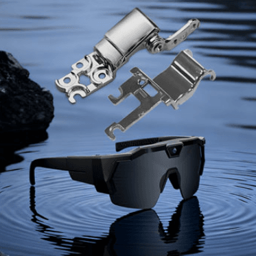
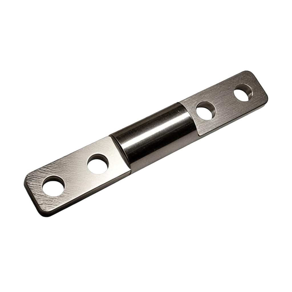
A friction hinge—also called a torque hinge or position hinge—uses internal friction to provide controlled rotational resistance. Unlike conventional hinges that simply connect two parts and let them rotate freely, a friction hinge does three things: it connects, rotates, and holds position on demand.
For a touch screen monitor arm, this “free-stop” capability is non-negotiable. The screen must stay where the operator puts it, without drift, sag, or the need for external locks, clamps, or gas struts.
Industrial monitor arms are not consumer display accessories. They support operator-facing HMIs, machine-control screens, warehouse terminals, inspection displays, and monitoring interfaces that must hold position reliably in real working environments. In these settings, the hinge must satisfy several requirements simultaneously:
- Repeatable angle holding – the display stays where positioned, without gradual drift
- One-hand repositioning – the monitor moves without excessive force, even in fast workflows
- Stable touch interaction – the screen does not shake or sag when the user presses on it
- Long-term consistency – movement feel and holding torque remain usable after many cycles
- Compact packaging – the motion-control solution fits inside space-limited industrial designs
Step 1: Calculate the Required Torque
Torque calculation is where most selection processes go wrong. The formula itself is straightforward, but the devil is in the details.
The Basic Formula
The minimum holding torque required at each hinge is:
T = (W × d) / n
Where:
- T = torque per hinge (N·m)
- W = weight of the monitor (N)
- d = distance from hinge pivot to the monitor’s center of gravity (m)
- n = number of hinges sharing the load
For example, if you have a 5 kg monitor (≈49 N) with its center of gravity 0.15 m from the hinge pivot, and you are using two hinges:
T = (49 × 0.15) / 2 = 3.675 N·m per hinge
The Safety Margin
Never spec a hinge at exactly the calculated minimum. Add a safety margin of 25–50% to account for:
- Manufacturing tolerances in both the hinge and the monitor
- Wear over the product’s lifecycle
- Temperature-related torque variation
- The additional force from touch interaction
A 13-inch touch screen typically requires at least 4.5 kgf-cm (≈0.44 N·m) of torque per hinge just to prevent collapse during touch operations. Larger screens and heavier displays require substantially more—some industrial monitor arms use hinges rated at 50 kgf-cm (≈4.9 N·m) or higher.
The Center of Gravity Trap
Do not select a hinge based only on screen size or advertised weight. A compact but front-heavy screen may need more torque than a larger but better-balanced display. For asymmetrical panels, panels with accessories, or panels carrying handles, fans, or reinforcement structures, always confirm the true center of gravity in CAD before final hinge selection.
Pro tip: A simple rule of thumb for a uniformly distributed panel: the torque is roughly half the distance from hinge to panel edge, multiplied by the weight. But for precision work, use CAD.
Step 2: Choose the Right Hinge Mechanism
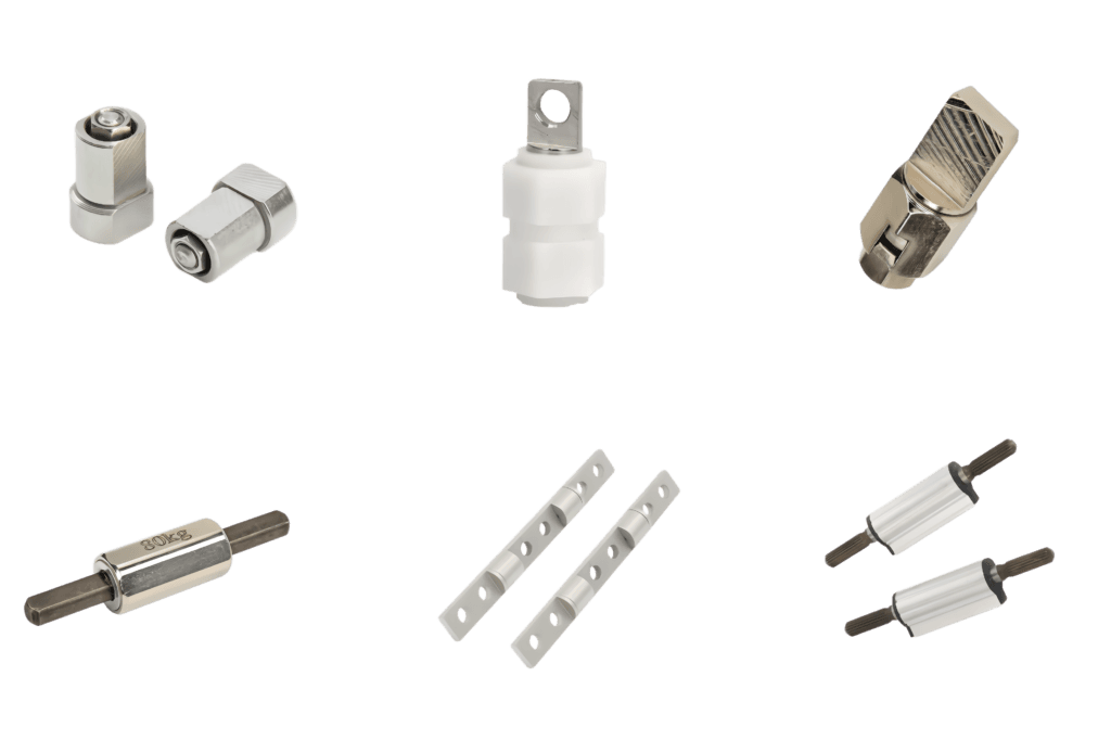
Not all friction hinges are created equal. Three mainstream mechanisms dominate the market, each solving fundamentally different engineering problems.
Spring-Clutch Mechanism
A hardened spring steel band—typically 301 stainless or beryllium copper—is tightly wound around a central shaft. The spring’s constant radial grip creates uniform friction at the shaft interface.
Strengths:
- Torque consistency across the full rotation range: ±15% or better
- Long cycle life: up to 50,000 cycles with zero readjustment
- Compact design
Weaknesses:
Best for: Medical monitor arms, aerospace applications, and any setting where torque consistency and cycle life are top priorities and field adjustment isn’t practical.
Interleaved Plate (Friction Disc) Design
Alternating friction discs, each keyed to opposite halves of the hinge, pressed together by a spring. When the hinge rotates, the discs slide against each other, and the cumulative friction produces the holding torque.
Strengths:
- Scalable torque: add more discs for more torque
- Modular and serviceable
- Wide torque range available
Weaknesses:
- More components mean more potential wear points
- Torque can vary more with temperature than spring-clutch designs
Best for: Industrial HMIs, control panels, and applications requiring moderate to high torque with reasonable cycle life.
Torsion Spring with Friction
A coiled spring wound around the pivot combines spring force with friction elements. The resistive torque varies with angular position—lower at neutral, higher at extremes.
Strengths:
- Simple, low-cost construction
- Good for applications with predictable load profiles
Weaknesses:
- Torque varies with angle, not constant
- Less suitable for free-stop positioning across full range
Best for: Laptop-style applications where increasing resistance at extremes is actually desirable.
Step 3: Select the Right Materials
Material selection affects durability, wear resistance, corrosion protection, and long-term torque stability.
Stainless Steel (304, 303, 316)
The default choice for most industrial applications. Stainless steel offers excellent corrosion resistance and good wear characteristics.
304 stainless is the most common. 316 stainless adds molybdenum for superior corrosion resistance in marine or chemical environments. High-strength alloy steels like SUS420J2 or 17-4PH are used for shafts to reduce material deformation under load.
Phosphor Bronze Washers
Often used as the friction interface in disc-style hinges. Phosphor bronze offers excellent wear resistance and consistent friction coefficients. Many Wixroyd hinges, for example, use phosphor bronze washers against stainless steel bodies.
Engineered Plastics (POM, PEEK, Glass-Filled Nylon)
Plastic friction components are used in lighter-duty applications or where corrosion resistance and low noise are priorities. Plastic-on-stainless configurations can provide consistent, low-wear operation across temperature ranges from −40°C to +150°C.
Surface Finish Matters
The shaft surface finish is a critical control parameter. For spring-clutch mechanisms, Ra 0.2–0.4 μm is the sweet spot where friction is stable without excessive wear. Go rougher, and torque becomes erratic. Go smoother, and you risk stick-slip.
Environmental Considerations
Do not default to stainless steel for every application. In high-acid or salt-fog environments, zinc die-cast hinges with sealed coatings can sometimes outperform stainless due to better galvanic compatibility with surrounding structures.
For outdoor or high-humidity environments, choose corrosion-resistant materials. For indoor, climate-controlled settings, you may have more flexibility.
Step 4: Evaluate Cycle Life and Testing
Cycle life is the number of open-close or adjustment cycles a hinge can survive before torque degrades below usable levels. This is where cheap hinges fail.
Industry Benchmarks
- 20,000 cycles is the industry standard for many commercial and light-industrial torque hinges
- 50,000 cycles is available from premium manufacturers
- 100,000+ cycles is achievable with properly specified spring-clutch mechanisms
For comparison, a basic zinc die-cast friction hinge might last only a few hundred cycles before torque drops below usable levels.
What “Cycle” Means
A cycle is typically defined as movement through a specified range—often 45° or 90° of rotation. Make sure you understand how the manufacturer defines a cycle and whether the test matches your actual usage pattern.
Torque Degradation Over Life
All hinges wear. But friction hinges wear faster than torque hinges, especially under oscillating motion. When evaluating a hinge, ask for test data showing torque retention after the rated cycle life. A good hinge should maintain torque within ±20% of its rated value over its lifecycle.
Step 5: Consider Adjustability
Fixed Torque Hinges
Factory-preset torque that cannot be changed in the field. Fixed torque hinges are simpler, lower-cost, and more reliable—fewer moving parts means fewer failure points.
Best for: Applications where the monitor weight and center of gravity are well-defined and will not change.
Adjustable Torque Hinges
Allow field engineers to fine-tune resistance after installation, compensating for seal drag, weight imbalance, or changes in loading. Adjustable torque hinges are available in ranges from 0.1 N·m up to 15 N·m or more.
Best for: Applications with variable loads, multiple monitor configurations, or where field serviceability is important.
One-Way vs. Two-Way Friction
One-way friction hinges provide resistance in only one direction of rotation. If the panel closes under its own weight, one-way is almost always sufficient.
Two-way friction hinges provide resistance in both directions. They cost more but are necessary when the panel must hold position against forces in either direction.
Step 6: Verify Installation and Integration
Mounting Constraints
Confirm available installation space, mounting orientation, and integration with surrounding structures. Touch screen monitor arms often have multiple hinge joints—base joint, elbow joint, and tilt joint—each with different torque requirements.
Temperature Range
Check the operating temperature range of the hinge. Typical ranges are -10°C to +50°C. Some premium designs extend from -40°C to +150°C.
Vibration Resistance
For forklift terminals, mobile inspection panels, vehicle-mounted displays, and vibration-prone machine HMIs, holding stability is paramount. The arm’s high rigidity makes it less prone to chattering—erroneous operation caused by shaking during touch panel operation.
Common Selection Mistakes to Avoid
Mistake 1: Selecting by Screen Size Alone
A compact but front-heavy screen may need more torque than a larger but better-balanced display. Always calculate based on weight and center of gravity.
Mistake 2: No Safety Margin
Specifying a hinge at exactly the calculated minimum torque leaves no room for manufacturing tolerances, wear, or temperature variation. Always add 25–50%.
Mistake 3: Ignoring Cycle Life
A hinge that works perfectly on day one but fails after 500 cycles is a warranty claim waiting to happen. Match cycle life to your expected usage.
Mistake 4: Mismatching Mechanism to Application
Using a basic friction hinge where a torque hinge is required leads to sagging or drifting. Understand the difference: friction hinges resist motion; torque hinges regulate it.
Mistake 5: Overlooking Touch Interaction Forces
A passive display and a touch screen are not the same load case. Touch screens see repeated, dynamic loading that can cause drift or shake in underspecified hinges.
Conclusion
Selecting friction hinges for touch screen monitor arms is a precision engineering task. It requires calculating torque based on actual weight and center of gravity, choosing the right mechanism type, selecting appropriate materials, verifying cycle life, and considering adjustability and environmental factors.
The stakes are high. An underspecified hinge leads to screen drift, operator frustration, and costly field service. An overspecified hinge adds unnecessary cost and complexity.
Get the hinge right, and your touch screen monitor arm delivers years of reliable, smooth, stable operation—exactly what your operators, technicians, and customers expect.
FAQ
Q1: What is the difference between a friction hinge and a torque hinge?
A: The terms are often used interchangeably, but there is a technical distinction. Friction hinges resist motion through surface tension between moving components—the resistance can vary with wear, temperature, and time. Torque hinges generate constant, predictable torque across the motion path using engineered internal components like springs or cams. For touch screen monitor arms, torque hinges are almost always the better choice because they deliver consistent holding force.
Q2: How do I calculate the torque required for my touch screen monitor arm?
A: Use the formula T = (W × d) / n, where W is monitor weight in newtons, d is the distance from the hinge pivot to the monitor’s center of gravity in meters, and n is the number of hinges. Then add a 25–50% safety margin to account for tolerances, wear, temperature effects, and touch interaction forces. Always confirm the center of gravity in CAD before finalizing your selection.
Q3: What cycle life should I expect from a quality friction hinge?
A: Industry standard for commercial and light-industrial torque hinges is 20,000 cycles. Premium spring-clutch designs can achieve 50,000 cycles with zero readjustment, and properly specified torque hinges can operate past 100,000 cycles without measurable degradation. In contrast, basic zinc die-cast friction hinges may fail after only a few hundred cycles.
Q4: Should I choose fixed or adjustable torque hinges for my monitor arm?
A: It depends on your application. Fixed torque hinges are simpler, lower-cost, and more reliable—best when monitor weight and center of gravity are well-defined and won’t change. Adjustable torque hinges are better when you have variable loads, multiple monitor configurations, or need field serviceability. Adjustable versions are available from 0.1 N·m to 15+ N·m.