In modern industrial design, automotive interiors, and premium consumer goods, the demand for smooth, controlled, and silent mechanical deceleration has elevated the rotary damper from a simple hardware accessory to a critical motion control component. However, many hardware engineers face recurring issues during product development and field testing: torque decay over extended cycles, structural fluid leakage, and erratic velocity deceleration under extreme operating temperatures.
This technical guide provides a deep engineering analysis of the fluid mechanics inside a rotary damper, practical mathematical formulas for torque calculation, an exploration of silicone oil viscosity behavior under thermal stress, and manufacturing strategies to mitigate critical failure modes.
1. The Physics of Rotary Dampers: Fluid Shear and Torque Generation
To design or select the optimal rotary damper, an engineer must first understand the underlying fluid mechanics that govern its operation. Unlike friction hinges, which rely on solid-to-solid mechanical interference to generate a constant holding force, rotary dampers utilize fluid shear stress to dissipate kinetic energy into thermal energy.
1.1 Structural Taxonomy: Vane Type vs. Gear (Continuous) Type
Rotary dampers generally fall into two architectural categories:
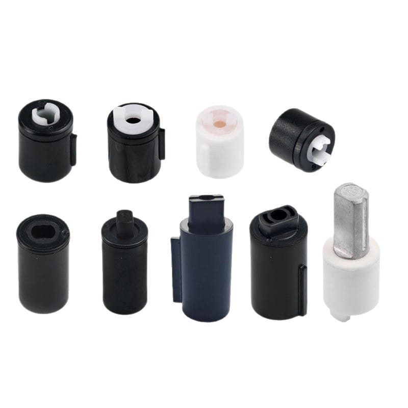
- Vane Dampers (Limited Angle): These dampers operate within a restricted angular movement (typically 90∘ to 180∘). Motion dissipation occurs as a rotor forces high-viscosity fluid through narrow orifices or bypass channels within a sealed housing chamber. Vane dampers are highly efficient for unilateral or bilateral damping in lid closures, armrests, and medical equipment panels.
- Gear/Wheel Dampers (Continuous Rotation): These components feature a rotor integrated with an external spur gear that interacts with a continuous viscous fluid layer surrounding an internal stator. They allow 360∘ continuous rotation and are ideal for linear gear racks, sliding trays, and motorized consumer electronics.
1.2 Fluid Shear Kinetics
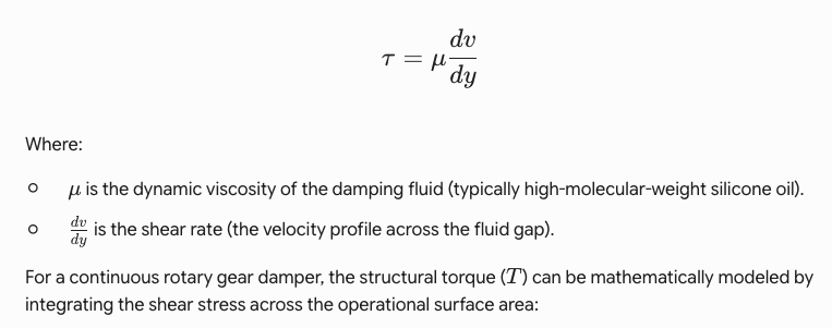
The torque generated by a rotary damper is fundamentally dependent on the shear rate of the fluid layer. According to Newton’s Law of Viscosity, the shear stress (τ) is proportional to the velocity gradient:
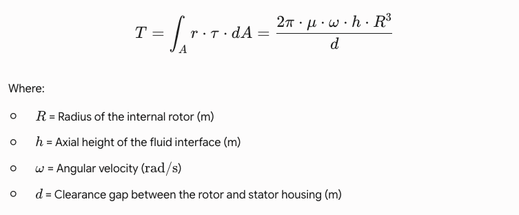
Engineering Insight:
The equation highlights a critical design reality: torque is inversely proportional to the clearance gap (d) and directly proportional to the cube of the rotor radius (R3). This means that a minuscule deviation of even ±0.01 mm in the injection-molded housing gap will cause an exponential shift in torque output. This mathematical fact underscores why precision tooling and automated molding consistency are non-negotiable for zero-defect production.
2. Thermal Stress and Viscosity Behavior of Silicone Fluids
One of the greatest challenges in motion control engineering is maintaining a consistent deceleration curve across varying environmental operating temperatures. Standard mechanical assemblies must perform reliably whether deployed in an automotive console exposed to sub-zero winters or an industrial control panel generating high internal heat.
2.1 The Viscosity-Temperature Coefficient (VTC)
Most rotary dampers utilize polydimethylsiloxane (PDMS) silicone oils due to their relatively flat viscosity-temperature curve compared to petroleum-based oils. The Viscosity-Temperature Coefficient (VTC) is calculated using the following formula:
VTC=1−Viscosity at 38∘CViscosity at 99∘C
For high-grade silicone oils, the VTC ranges from 0.58 to 0.62, meaning that while the viscosity does drop as temperature increases, it remains far more stable than organic lubricants.
2.2 Thermal Torque Deviations: Real-World Scenarios
Despite the stability of silicone oil, extreme temperatures still impact damper performance:
| Temperature Environment | Fluid Reaction | Impact on Mechanical Assembly |
|---|---|---|
| Low Temp (−20∘C to −40∘C) | Viscosity climbs exponentially. Internal molecules compress. | Increased initial breakaway torque. The lid or drawer opens sluggishly or fails to open fully via spring return. |
| High Temp (+60∘C to +80∘C) | Polymer chains expand, thinning the fluid. | Decreased damping resistance. Kinetic energy absorption drops, causing the lid to slam and fail its soft-close function. |
2.3 Mitigating Thermal Drift through Precision Volumetric Design
When silicone fluid transitions from room temperature (25∘C) to 80∘C, it exhibits thermal expansion. If a damper chamber is filled to 100% volumetric capacity without accounting for expansion coefficient variables, the internal hydraulic pressure will spike under high heat, forcing fluid past the rubber sealing rings.
To engineer around this, professional manufacturers apply a two-step remedy:
- Controlled Volumetric Underfill: Calculate the precise fluid volume required at peak thermal expansion, leaving a micrometric air cushion or internal expansion pocket without introducing aeration bubbles into the primary shear zone.
- Apparent Viscosity Compensation: Utilize non-Newtonian shear-thinning fluids where the viscosity adapts to changes in structural speed, stabilizing the perceived kinetic resistance across erratic ambient shifts.
3. Root Cause Analysis of Common Rotary Damper Failure Modes
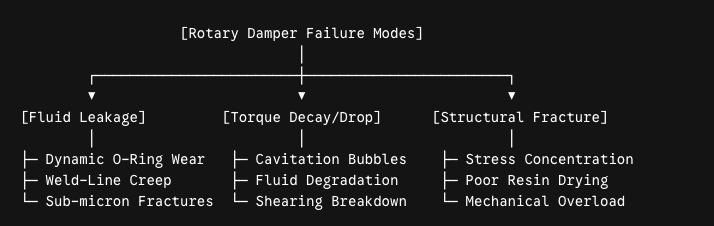
For procurement managers and quality engineers, assessing a supplier involves understanding how they proactively eliminate field failures. Below is an engineering root-cause analysis of the three most common failure modes found in low-grade rotary dampers.
3.1 Failure Mode 1: Fluid Leakage (The Zero-Tolerance Issue)
Fluid leakage is the absolute point of failure for any viscous damper; once silicone oil escapes, the mechanism loses all resistance and can contaminate surrounding cosmetic or electronic components.
- Root Cause A: Improper Dynamic O-Ring Compression. The interface between the rotating shaft and the static outer housing is sealed by an elastomeric O-ring (typically NBR or FKM Fluorocarbon). If the dynamic compression ratio is too low, fluid escapes under thermal expansion. If it is too high, friction spikes, causing premature wear and seal shredding.
- Root Cause B: Weld-Line Failures in Ultrasonic Housing Caps. Many rotary dampers seal their fluid chamber by ultrasonically welding a plastic cap onto the main housing. If the ultrasonic welding horn parameters (energy, pressure, collapse depth) are not precisely controlled, sub-micron fractures or weak weld lines form, which yield under continuous internal hydraulic pressure.
3.2 Failure Mode 2: Torque Decay Over Extended Lifecycles
When a rotary damper performs perfectly during initial inspection but loses 30% to 50% of its torque resistance after 10,000 cycles, it suffers from torque decay.
- Root Cause A: Mechanical Cavitation and Air Entrapment. If the fluid filling process is conducted in an open-air environment rather than an industrial vacuum chamber, micro-bubbles of air become trapped within the silicone oil. Under continuous rotation, these bubbles coalesce into larger air pockets. When the rotor passes through an air pocket instead of the silicone oil film, resistance momentarily drops to zero, destroying the smooth tactile feel.
- Root Cause B: Molecular Shearing of Damping Fluid. Low-quality silicone fluids are composed of inconsistent, unstable molecular chain lengths. Under high continuous shear stress, these long polymer chains literally rip apart, resulting in a permanent reduction in apparent viscosity and an irreversible drop in torque output.
3.3 Failure Mode 3: Plastic Housing Structural Fracture
When subjected to unexpected external loads or sudden impact forces, the outer gear teeth or mounting tabs of the damper can shear off completely.
- Root Cause: Residual Internal Mold Stress. Improper injection molding parameters—such as excessive injection pressure, inadequate melt temperatures, or rushed cooling cycles—leave high residual stress locked inside the crystalline structure of technical resins (like POM or PA66-GF30). When an external mechanical load is applied, these stress concentration points act as nucleation sites for rapid structural cracking.
4. Advanced Manufacturing Infrastructure: Engineering Solutions for Long-Term Reliability
Eliminating the aforementioned engineering failures cannot be achieved through final product screening alone; it must be baked directly into the manufacturing infrastructure and automated assembly lines.
4.1 Vertical Integration: Tooling, Injection Molding, and Die-Casting
True consistency in motion control parts requires total control over component tolerances. Sourcing plastic housings from third-party molders frequently introduces lot-to-lot dimensional variance that disrupts the ultra-precise rotor clearance gap (d).

By utilizing a fully integrated in-house manufacturing process, engineers can synchronize tooling design with real-time injection molding parameters. Advanced multi-cavity hot-runner molds running on high-precision European or Japanese electric molding machines ensure that roundness tolerances, concentricity of the central bore, and gear tooth profiles are held within ±0.005 mm. This precision directly stabilizes the fluid gap boundary layer, guaranteeing uniform torque from unit 1 to unit 500,000.
4.2 Material Selection Science: Reinforced Resins and Elastomers
To maximize torque handling and structural durability:
- Housings and Rotors: Specialized Polyoxymethylene (POM) copolymer resins or Glass-Fiber Reinforced Polyamides (PA66-GF30) are selected for their exceptional dimensional stability, low water absorption coefficients, high fatigue resistance, and low coefficient of friction against dynamic shafts.
- Dynamic Seals: Synthetic Nitrile Rubber (NBR) with optimized shore hardness (typically 70-80 Shore A) or Fluorocarbon (FKM) compounds are used to withstand continuous friction, resist silicone oil swelling, and maintain elasticity from −40∘C up to +120∘C.
4.3 Rigorous Process Controls & Testing Protocols
To satisfy stringent automotive (IATF 16949) and industrial (ISO 9001) quality baselines, every manufacturing lot must undergo a battery of stress tests designed to simulate severe real-world lifetimes:
- Vacuum De-aeration and Fluid Dispensing: Rotary damper fluid injection should happen inside a computer-controlled vacuum chamber. This pulls all atmospheric gasses out of the chamber, allowing the high-viscosity silicone fluid to completely wet all internal surfaces with zero air inclusion.
- 100% In-Line Torque Characterization: Every single rotary damper must pass through an automated testing station where an electronic servo actuator rotates the damper shaft at a fixed angular velocity (ω) while a high-resolution load cell logs the dynamic torque profile. Any unit deviating by more than ±8% from nominal specifications is automatically rejected.
- Environmental Life-Cycle Chambers: Randomly sampled units from every production lot must run continuously inside environmental chambers for up to 50,000 to 100,000 cycles at peak operating thermal extremes, confirming that torque decay remains well within acceptable engineering margins (<15%).
5. Mathematical Calculation Framework for Engineering Selection
When proposing a rotary damper for a gravity-drop lid assembly (such as a soft-close appliance door or an automotive glove box), engineers must match the damper’s torque rating to the maximum closing torque generated by the application.
Below is the step-by-step mathematical model used to determine the necessary damper torque requirements.
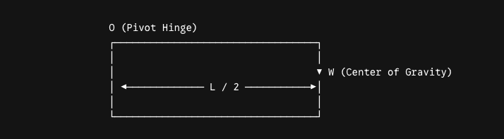
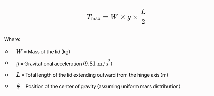
Step 1: Calculate Maximum Static Torque Generated by the Lid
The maximum torque (Tmax) occurs when the lid is in a horizontal orientation (90∘ relative to the vertical gravity vector), where the distance from the pivot hinge to the center of gravity is maximized.
Step 2: Account for Angular Velocity and Target Closing Time
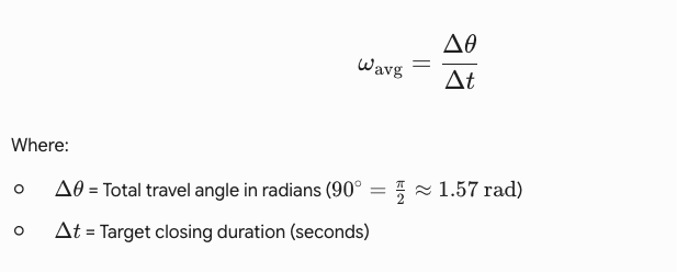
Because a rotary damper’s resistance increases with speed, engineers must specify a target closing time (e.g., 3 to 5 seconds for a 90∘ descent). The average angular velocity (ωavg) is defined as:
Step 3: Match with Factory Torque Performance Curves
Using the calculated Tmax and ωavg, the design engineer references the manufacturer’s RPM-vs-Torque charts. Selecting a damper with a nominal torque value matching this intersection point ensures a smooth, constant-velocity soft-close movement without stuttering or sudden acceleration.
6. Conclusion & Engineering Consultation
The performance of a high-end application depends entirely on the stability of its moving parts. Designing an effective soft-close mechanism requires managing clearances, choosing high-performance materials, and maintaining strict control over production tolerances. Minimizing torque decay and preventing fluid leakage requires deep engineering experience and specialized manufacturing capabilities.
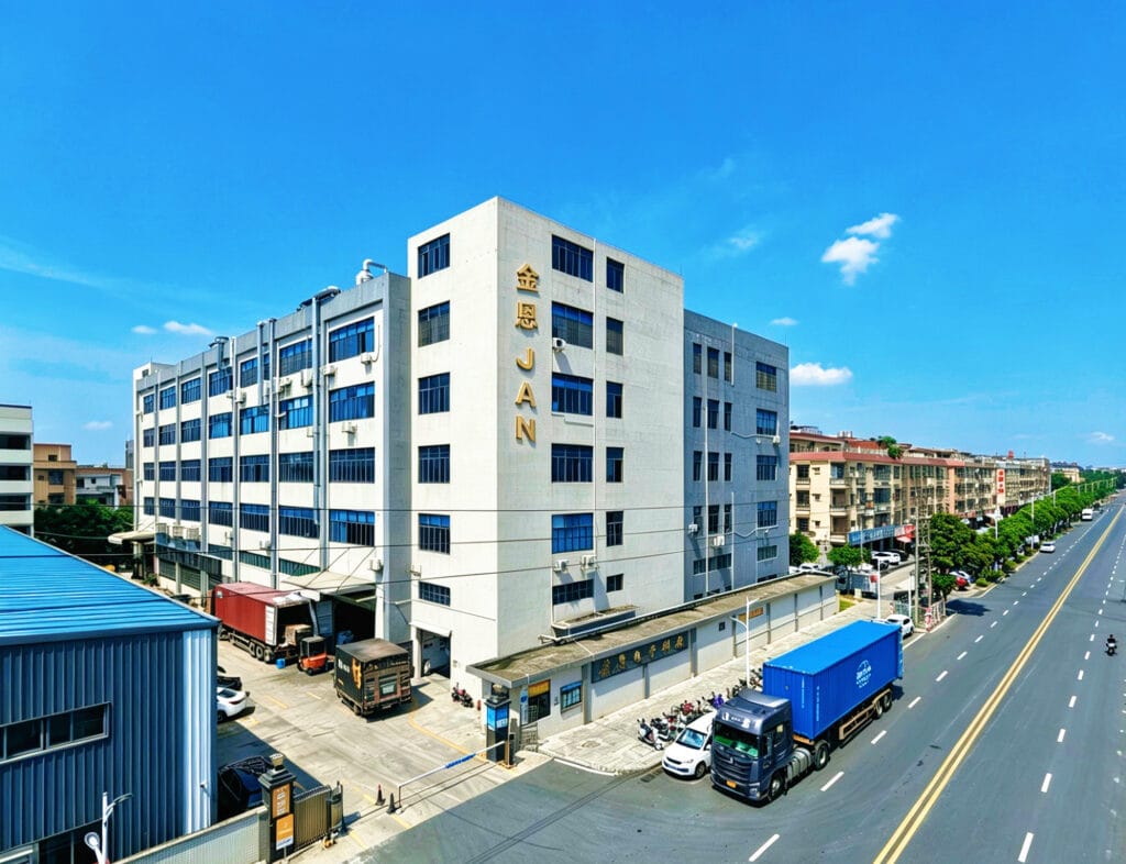
About JAN (Jin En Intelligent Technology): As a vertically integrated, IATF 16949 and ISO 9001 certified manufacturer, JAN specializes in high-performance motion control components. Operating from our 3,000-square-meter facility with an engineered daily capacity of 500,000 units, we manage the entire production cycle in-house—from custom tooling design and precision injection molding to automated vacuum fluid filling and 100% torque testing. Backed by 11 years of dedicated R&D and manufacturing expertise, our engineering team works directly with global tier-1 automotive, appliance, and electronics designers to solve complex damping challenges.
Need a dedicated technical evaluation or custom 3D CAD models for your next design project? Contact our engineering lead today at www.janhinge.com to access our rapid prototyping and direct-from-factory technical consulting services.